Wiring and running TB6600 stepper driver with Arduino
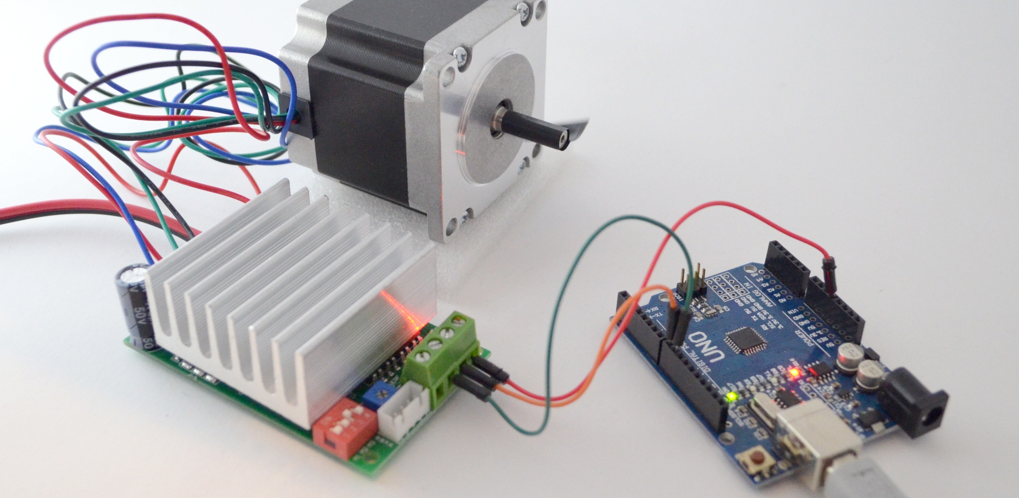
A quick post about wiring TB6600 stepper driver which is based on TB6600HG chip. Here I use one without black plastic casing. It has model marking on the back that says “BL-TB6600-v1.2″. Stepper motor used in this demo is 23HS22-2804S (2.8A, NEMA23). Drive looks like this and it’s rated for 4.5A.
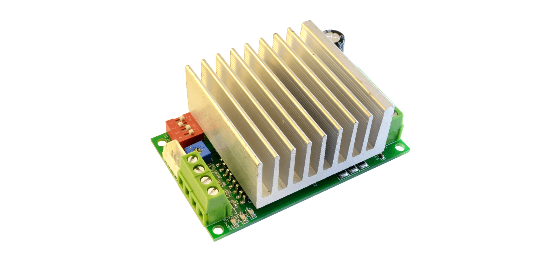
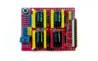
TB6600 v1.2 green PCB
Looking for more info and photos? Check out my previous post about TB6600 drive where I removed heatsink covering the whole PCB.
Wiring TB6600 and Arduino
Terminals on the drive are clearly marked and there is nothing much you can go wrong with. Power supply should be between 8V to 42V (by chip’s datasheet). Low voltage cut-off was actually around 6.5V when I tested it. You have to find paired wires of your stepper motor and connect them to drive’s A+ A- and B+ B- terminals. From Arduino, I had to connect only 3 wires.
- Arduino +5V to +5V on the drive
- Arduino Digital pin 9 to CW (direction) on the drive
- Arduino Digital pin 8 to CLK (pulse, step) on the drive
I left enable pin disconnected for testing.
If you are a beginner and want more in-depth info – check out my other post on how to drive a stepper motor.
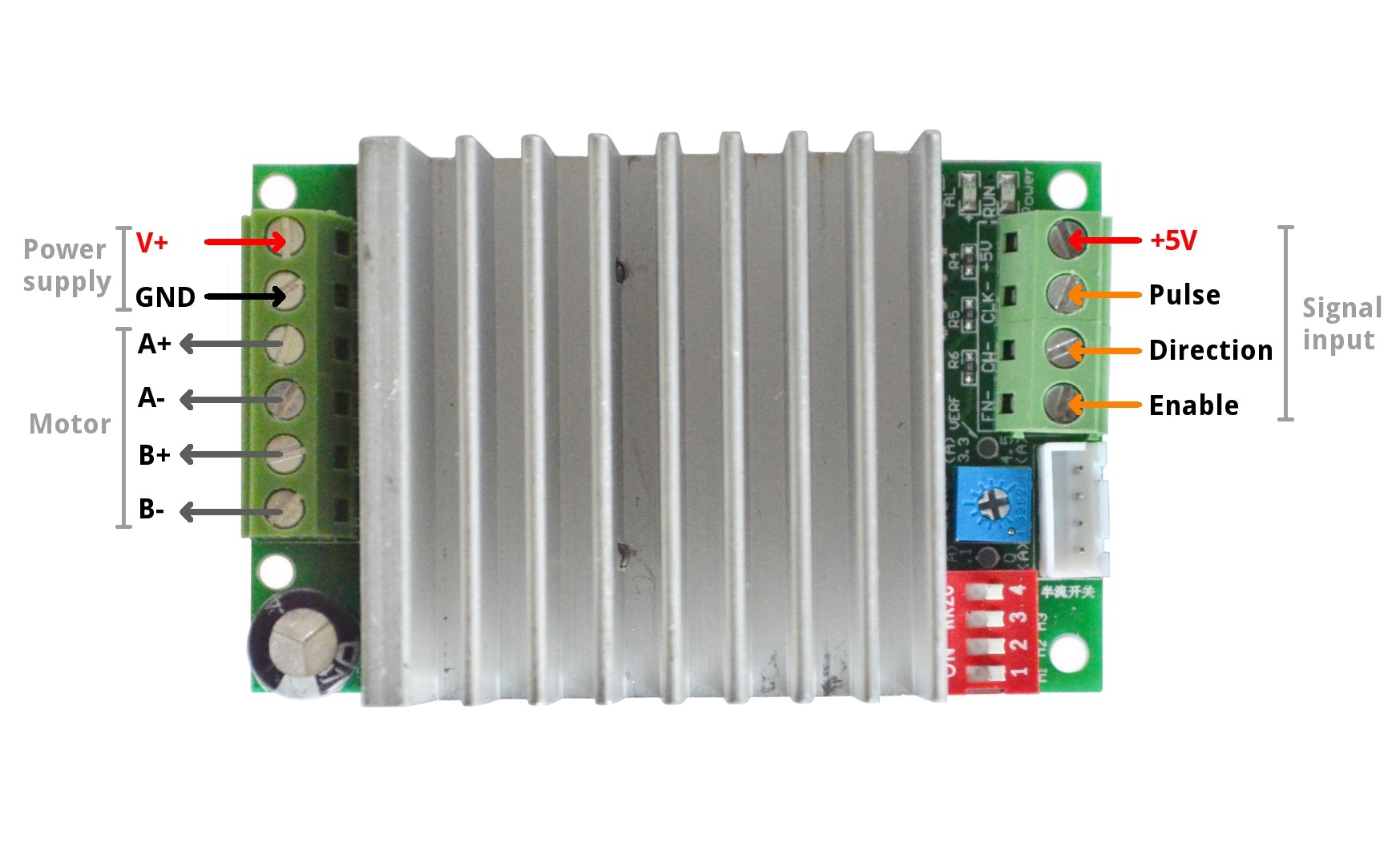
Wiring TB6600 (4.5A drive), input / output diagram
Programming Arduino
I used AccelStepper library to make the motor run smoothly for testing. The program I used was Bounce which is one of the example code snippets from that library. Here is the final Arduino sketch I used to make the demonstration video at the end.
#include <AccelStepper.h>


// Define a stepper motor 1 for arduino
// direction Digital 9 (CW), pulses Digital 8 (CLK)
AccelStepper stepper(1, 8, 9);
void setup()
{
  // Change these to suit your stepper if you want
  stepper.setMaxSpeed(1000);//1100
  stepper.setAcceleration(1100);
  stepper.moveTo(2000);
}

void loop()
{
    // If at the end of travel go to the other end
    if (stepper.distanceToGo() == 0){
      stepper.moveTo( -stepper.currentPosition() );
    }

    stepper.run();
}
TB6600 microstepping settings
Note about dip switches on board. When I hooked everything up for the first time- I didn’t get it working. I was bit confused. That happened because I had all dip switches in off state. I thought that if everything is off- there is no microstepping applied. But with TB6600 it means the drive is disabled. Here is a screenshot from the datasheet for quick reference. Grab the whole datasheet from here.
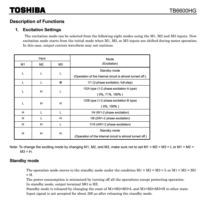
Screenshot from TB6600HG datasheet about microstepping and standby settings
Video
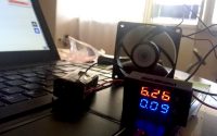
And here is the video of this combo running.
why my tb6600 v102 is not reversing in rotatation?
i’m working to control the stepper motor angle of rotation. which i want it to rotate at 45 degree. can you help me in doing this as i use arduino, tb6600 motor driver and a stepper motor. thank you.
Just send correct amount of pulses to driver and it turns as much you want.
So if you have stepper motor with 1.8° step angle it’s 25 pulses and if you have stepper motor with 0.9° step angle it’s 50 pulses. Keep in mind this logic only applies when you have no microstepping applied in driver (full-step mode is on).
So if you use same library like I did for this test you need to send following steps/pulses to driver:
Nice post. Keep update friends
Hellow i am using 4 Steper moter in z axis so we connected 2 mks tb6600 but its not work properly please tell mi solution I connecte 2 driver but not working properly
I don’t understand your setup. You should be more specific in your question. And what you mean by – not working correctly? What are the symptoms? I suggest you ask some forum about it since it seems a complex problem and I can’t answer it currently.
Hi there i’m using stepper motor driver TB6600. My driver have Pul+ Pul- dir+ dir- en+ en- .so if i want to proceed with ur test how should i connect the wiring.Thank you
Seems that you have bit different out pins and drive. More like this one probably https://discuss.inventables.com/t/please-help-tb6600-wiring/33068/15 ? I guess the connections pointed by “B.F” is probably correct ones @ that page.
Seems that pulse +, direction + are all wired to microcontroller’s + side. And pulse negative and direction negative are wired to microcontroller pins for fir/pulse.
AccelStepper stepper(AccelStepper::DRIVER, 8, 9); // 8 = PUL-, 9 = DIR – [as AccelStepper stepper(AccelStepper::DRIVER, 8, 9)
// PUL+, DIR+ both connected to 5V in arduino
// ENA+, ENA- = no connection required.
try this setup , works fine.
Please help and give me marlin. ino for this test. I am used arduino mega 2560 and ramps1.4, thank you
Please help and give me marlin. ino for this test. I am used arduino mega 2560 and ramps1.4, driver tb6600 v1.2 and nema23 thank you
I don’t understand your question very well. Marlin is not the case here. I guess you want to hook it up to ramps instead of DRV8825?
You just have to remove drv8825 from their sockets and connect driving pins (step/dir) to the external drives. Something like here: https://reprap.org/forum/read.php?219,652190,653617#msg-653617 (this is not example with TB660, but logic is pretty much the same)
Please help me, wiring ramps1.4 to stepper driver tb6600, Because I have tried several wiring diagrams, but the stepper motor is still not working, thank you ,
Have you tested stepper motor and tb6600 drive without ramps before? So that part of the system is confirmed working? If not – check your jumper settings (at least one of them must be switched to HIGH from M1, M2, M3).
Basically what I am asking – id you get this stepper + TB6600 working (with arduino) before adding ramps into the mix?
For our project, we have to provide variable dc voltage depending on the input signal from arduino and some sensors. Can we use this driver to vary the voltage?
If not, please suggest something else.
Our output power requirements are 30V, 5A.
I am not sure of the intent of the question / did I understand it correctly. So you want to use the drive for “regulating” output voltage? This is a stepper drive in this article- not a DC motor speed regulator (trough voltage). Probably you are looking for DC motor speed (voltage) controller which uses PWM input from Arduino to regulate it. Stepper drive is not suitable for that.
What are you using to power the stepper?
Hi. Whatever power supply that can output 8V – 42V and enough amperes to drive my motor. This drive can handle as much of 4.5 amperes. 12V computer power supply is often OK to test out the system, but a higher voltage is preferred for speed and performance.
hi
my question is how to connect four tb6600 drivers into a single arduino board. i’ve been planning to build a hot wire foam cutter but my four axis cnc driver board had issues. i’m now planning to switch to individual drivers for each motors and an arduino board to connect the drivers. can u help me out on the connections and the coding for arduino. TIA
Hi. Why is the arduino not connected to ground & should it be?
This is actually an excellent question- and I don’t know the answer. I can’t remember how this test was set up. But I am pretty sure that Arduino and the drive had separated power supplies. But I am totally confused by it now. Indeed – how does it work when there is no common ground. I have to test this (I think I have one of these drives somewhere)
Hi do you have an answer for this? Mine isn’t working and I am assuming because there is no ground. I first thought and I think I still do think I need to be in pulldown mode where if I read the pin then it activates for that pin because current may flow there is no other way it works. But I’m not sure if its that method or another.
I USED AN LM398 DRIVER TO CONTROL MY STEPPER MOTOR. I USED Stepper.h HEADER FILE AND IT IS WORKING.
CAN I USE THE SAME CODE WITH THIS TB6600 DRIVER? WHY?
Hi,
thanks for the very usefull information.
I have 1 question: I would like to use the TB6600HG chip in my own PCB design and I would like to connect the pins ( EN,RES,CLK,DIR ,TORQUE,LATCH, M1,M2 and M3) directly to a microprocessor.
Is that possible? I can not find any schematics, for a pure TB6600HG chip, without a OptoCoupler.
Best regards
Andreas
Hi.
I don’t have an example to give myself, but example application is in datasheet on page 31 ( https://toshiba.semicon-storage.com/info/docget.jsp?did=14683&prodName=TB6600HG ). I have not used bare chip myself- only this breakout board in this article. If you can – work out yourself how to connect it with microcontroller via pinout and data given in datasheet. Most likely it’s possible.