How to drive a stepper motor- simplified beginner’s guide with common questions
You are planning your first 3D printer, CNC router or some other machine which needs accurate positioning. Looking around leads you to a lot of people talking about stepper motors. But what are they exactly and especially- how to drive a stepper motor?
I have gathered some basic misconceptions and questions people have asked me over time about driving stepper motors. Starting with the high-level logic behind running a stepper motor and ending with some common questions and problems.
Consider this as a simplified beginner’s guide. I don’t go into the deep technical and calculation side of things which can get very complicated and application dependent. You can learn all that later. Your current mission is most likely to get the motor running and understand the basics behind running stepper motors.
Table of contents for quick reference
- What is a stepper motor?
- What do you need to get a stepper motor running?
- What you need to know about the motor and drive types
- How to Wire a stepper motor to a driver
- Common questions, problems, and misconceptions
- How to run a stepper motor without a microcontroller?
- How to rotate stepper motor 90 degree (or any other degrees)
- How can we control the speed of stepper motor?
- Can stepper motors run continuously?
- What is holding torque (current) and why it’s needed?
- What driver do I need to run NEMA 17 motor (or NEMA 24, etc)?
- Final words
What is a stepper motor?
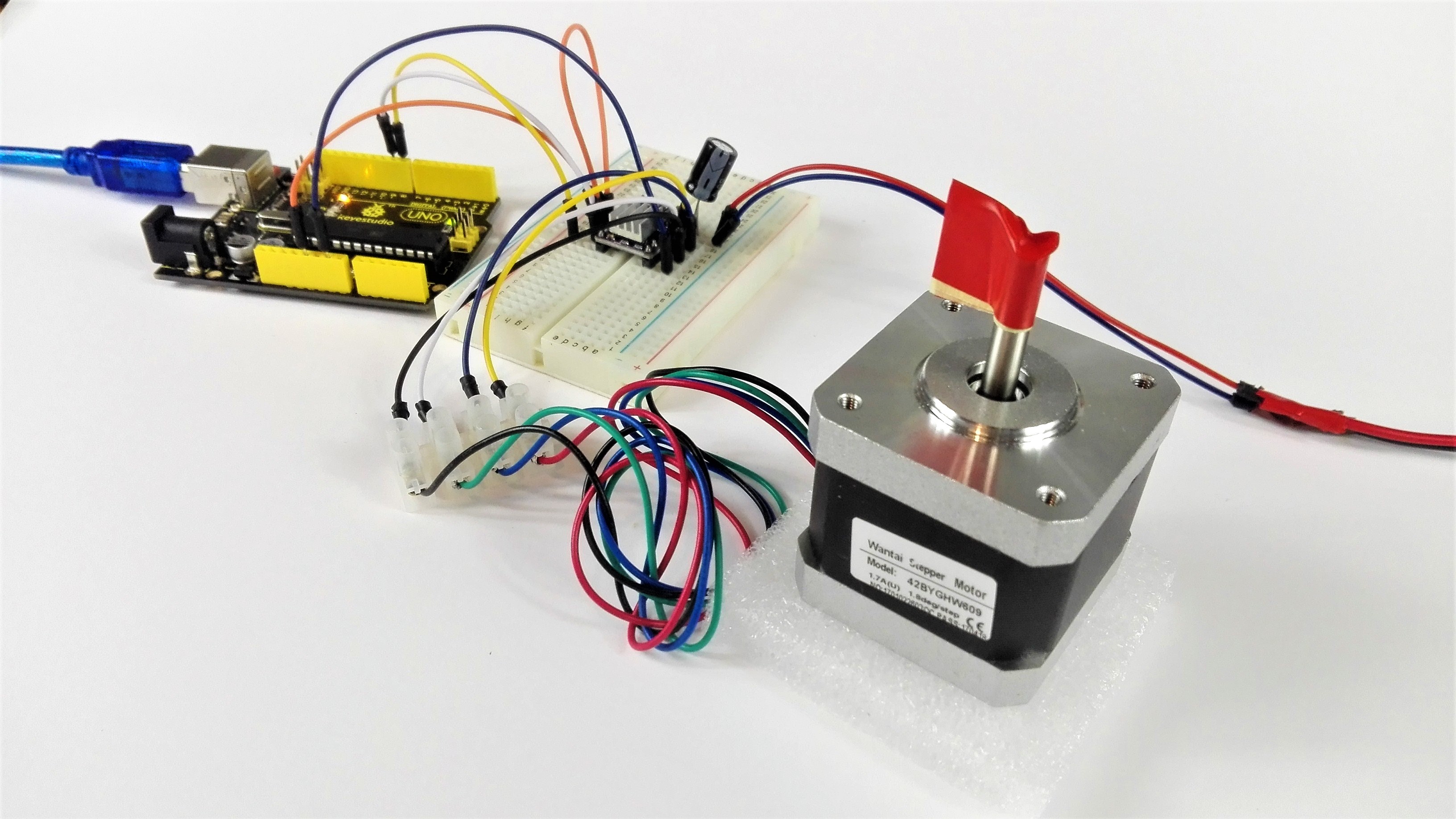
There is a lot of resources online which go into great detail about different types of stepper motors and how they work. Check out, for example, this article about stepper motor types. But this is not important at moment. What you need to know is that stepper motors are not your average DC motors. They will not run by hooking up directly to the power supply. They usually have 4 wires, but there is also a 5, 6 and 8 wire motors.
Stepper motor’s rotation is controlled by exciting coils in correct order and polarity. The motor moves exactly one small predefined angle (called a step) each time coil(s) in motor get excited. But motor will not run continuously- it holds the position while powered. Step angle is usually 1.8 degrees. This means you have to make 200 steps to make a complete 360-degree turn (1.8 * 200). Check out this excellent video on youtube which visualizes driving stepper motor by energizing coils in the correct order.
Even though they are used for accurate positioning, they don’t have any position feedback mechanisms like servos have. But if used correctly- there is no need anyway. Controlling rotation and position is done through making correct amounts of steps.
What do you need to get a stepper motor running?
Following chapter is a very high overview. Please read further down about more practical info about the drive and motor types. But basics presented here is pretty universal and widely used in DIY community.
So- what we need to get these motors going? Let’s break it down to components and explain each part briefly. Commonly you need following parts to drive a stepper motor.
- Driver
- Microcontroller
- Power supply
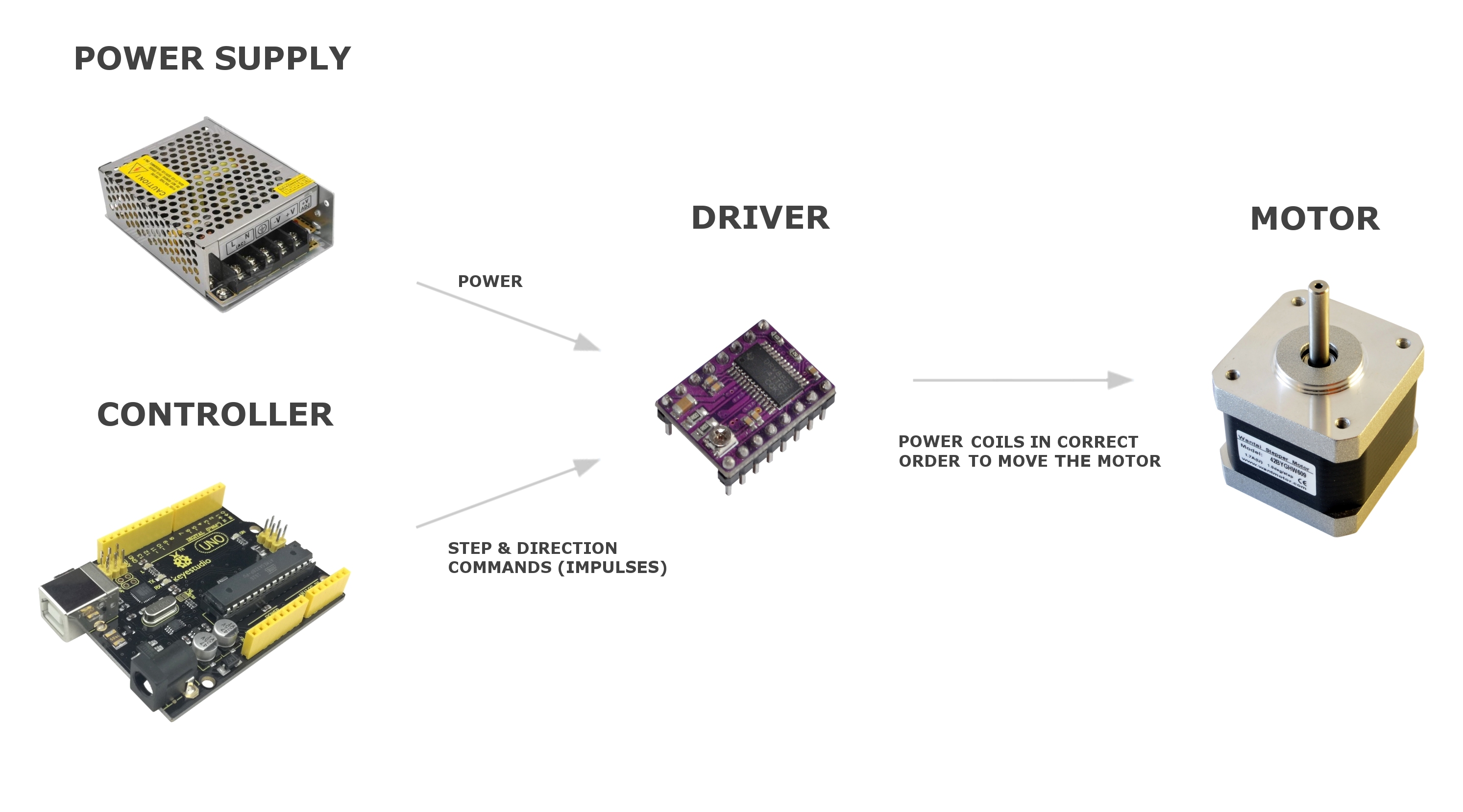
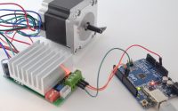
High overview of components needed to drive a stepper motor
I didn’t include a power supply for (micro)controller here since it’s self-explanatory. A microcontroller like in this case Arduino- gets its power from the USB cable or battery.
Driver
As we know- stepping motor can be moved one step at a time by applying electricity to coils in the correct order (and polarities). You could do this manually with some switches– step by step, but it has no practical use other than learning. This is where the driver comes into play.
The driver is doing the heavy lifting and it hides all the complexity behind a simple interface. It makes correct windings to be excited in the correct way based on the input signals. They usually have only 2 input pins which take commands in form of digital high and low. One sets the direction of rotation and other is for step commands.
But it’s not as simple as connecting steps pin into logical HIGH and expect the drive to move motor continuously. It would still make only one step.
Steps are given as digital pulses. After each step (HIGH) there must be (LOW) input for a moment. So drive can detect when new step command is given. If there is are no pulses given- there will be no steps done by the drive and motor.
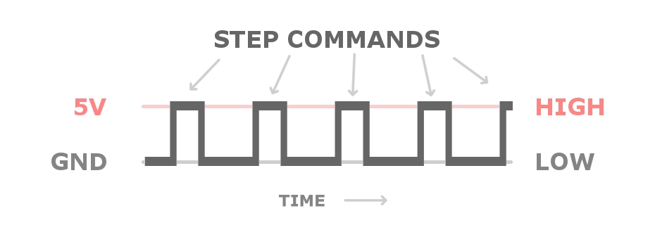
Digital signal LOW/HIGH example
Direction input pin can be LOW or HIGH all the time, while steps are made, depending on the direction needed. Direction does not need impulses.
Note: Some small unipolar motors are driven via transistor arrays or chips like uln2003 and ln2004. There can be 4 control wires instead of 2 from the microcontroller. In that configuration, the microcontroller is directly telling which wires (coils) to energize by turning correct ones on each step “manually”. Look at example schema on the Arduino page.
Microcontroller
It’s possible to make motors move by touching the step pin on driver manually with HIGH wire. But that would not be very practical other than testing. This is why microcontroller comes into play. Microcontrollers can give many hundreds or even thousands of impulses per second so the motor can be rotated very fast and accurate.
The controller itself does not know how you want to move your motor to be useful. Some kind of software (firmware) must be installed on the controller. If you are building CNC router or a 3d printer you can use software already written by others. For example:
- GRBL for CNC https://github.com/grbl/grbl
- Marlin for 3d printer http://marlinfw.org
When creating some custom thing you need to have to dig into programming. For testing, a very simple program can be used which just steps motor in one direction. Here is an example code for Arduino.
// Define Arduino pins for STEP and DIRECTION
const int dirPin = 8;
const int stepPin = 9;

//Define delays between commands, you can play with these
const int delayStepCommandInMicroSeconds = 50; // Time STEP will be HIGH (pulse)
const int delayBetweenStepInMicroSeconds = 1200; // Time STEP will be LOW

void setup() {
  pinMode( stepPin, OUTPUT);
  pinMode( dirPin,  OUTPUT);
}

void loop() {

  // Enables the motor to move in a particular direction
  // Remove // to change motor direction
  // digitalWrite( dirPin, HIGH );

  // make 200 pulses which correspond to 360
  // degrees (one full rotation) when using
  // 1.8 step degree motor in full-step mode
  for( int x = 0; x < 200; x++ ) {
    digitalWrite( stepPin, HIGH );
    delayMicroseconds( delayStepCommandInMicroSeconds );
    digitalWrite( stepPin, LOW );
    delayMicroseconds( delayBetweenStepInMicroSeconds );
  }

  //Wait one second in a standstill and start over from top
  delay(1000);
}
For simpler applications, it’s probably enough, but anything that handles heavier loads and more complex operations you should use some library. For Arduino, you can use AccelStepper library. Check out my simple example code with TB6600 driver. There you can see features like acceleration and setting maximum speed.
Power supply
You need an external power supply for most drives and motors. Some small Arduino kit motors can be run on USB/Arduino power as “28BYJ-48”. But everything bigger needs more power and voltage. For testing, most likely you can use average computer or laptop power supply.
What you need to know about the motor and drive types
In the previous section, I explained a high-level overview of how stepper motors are driven. But it’s more complicated than just hooking things up. There are different types of drives, motors and wiring schemas.
Bipolar and unipolar motors
Broadly speaking, there are 2 types of stepper motors – bipolar and unipolar. The difference is how coils inside the motor are wired up and how they can be energized to get correct magnetic poles for each step. It all boils down to a simple question. How many wires does a stepper motor have? Based on wires which come out of motor we can determine what kind of motor it is and what kind of drive we need to run it.
A 4-wire motor can be only driven by the bipolar drive. 5-wire motor can only be driven by the unipolar drive since center taps are tied together internally. Motors with 6 and 8 wires can be used with both drive types since you can decide how to hook them up externally.
The difference is how coils inside motors are energized. In the bipolar motor current (polarity) must be reversed in wires for each step. Unipolar motors achieve pole reversal trough center taps in coils, but only energizing half of the coil same time. Adafruit has a good article about unipolar vs bipolar motor coils and wiring. It’s definitely a plus if you make yourself familiar with how they differ.
Driver types
Other than being unipolar and bipolar drives- there are also different ways how they control current and voltage in the motor windings. Primary types are the following:
- constant voltage drives also referred to as L/R drives
- constant current drives also referred as chopper drives
I don’t go into detail about unipolar drives or constant voltage drives since most likely you end up with a constant current driver with a bipolar motor. Chopper drives are the most popular these days because of the torque and speed limitations of L/R stepper drives.
Chopper drive benefits
When using a chopper drive, the nominal voltage of the motor is mostly irrelevant for practical purposes. At least for hobby user and Arduino enthusiast. So don’t get scared away from stepper motor based on very low rated voltage. The important figure is the rated current.
A chopper drive can run the stepper motor with much higher voltage than the motor’s rated voltage. Higher voltage allows the current to flow through the stepper motor faster, which gives the ability to turn it faster with more torque. Drive keeps current in the motor below the fixed value which keeps motor burning out. Additionally- higher voltage means less heat.
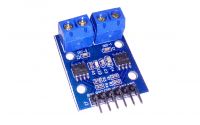
Fixed current is usually set by trimmer pot on the drive board. That allows you to change maximum current based on needed torque and rated current by motor specs.
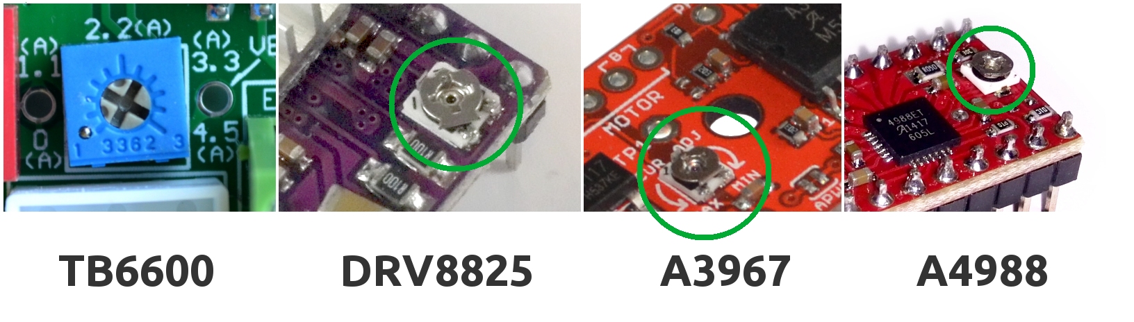
Current limiting potentiometer examples on (chopper) stepper motor drives
How to Wire a stepper motor to a driver
There are 2 configurations. I only explain the bipolar more in-depth currently but will add unipolar also some day. Bipolar configuration is more popular anyway these days.
Connecting 4 or 6 lead stepper motor in a bipolar configuration
The 4-wire stepper motor is easiest and most popular configuration these days. You only have to find out which leads form a pair. Easiest is to use multimeter and measure resistance between wires that are coming from the stepper motor. 4-wire motor is easiest. If there is no reading it’s not connected. If you get reading- it’s a pair. You can even do it without multimeter by just turning motor while touching wires. Whichever combination makes motor harder to move- is a pair.
In a 6-wire motor, you have to find outer leads and skip the center common leads. Center leads will be exactly 1/2 of the resistance than the outer leads. Just start testing lead pairs and find out which leads make up pairs with most resistance.
These 2 pairs can now be connected to the drive. Usually, these pairs are called A and B. In my example they are wired to a bipolar A3967 drive where there is clear marking which leads go to where. Sometimes connectors on the drive are marked as A1, A2 and B1, B2. Sometimes they are marked A-, A+ and B-, B+. It doesn’t matter which way you connect wires within one pair. It only changes the rotation of the motor.
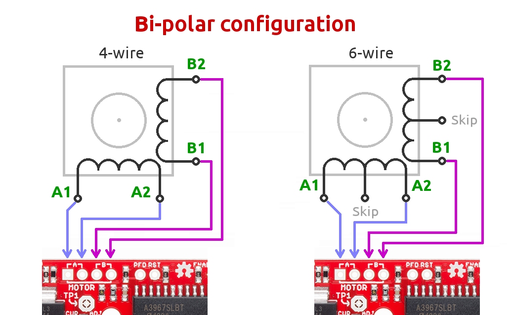
Wiring schema for 4-lead and 6-lead stepper motors with A3967 bipolar drive
Connecting 5 lead or 6 lead stepper motor in a unipolar configuration
A 5-wire stepper motor can only be wired as unipolar. 6-wire motor can be used both. To use 6 wire motor in a unipolar configuration you only need to connect center taps together. And that connected center taps will be the fifth wire and you can use it as 5-wire stepper.
Unipolar stepper motor wiring to the drive is a bit harder. You have to find out the correct order for wires. Otherwise motor will only step forward and backward. Go look this video on youtube which is very easy to follow and explains greatly the process of finding correct order.
Common questions, problems, and misconceptions
I have listed some common questions people have asked me and forums. Let me know if I have missed something big from the list.
How to run a stepper motor without a microcontroller?
It’s totally possible since the drive doesn’t care where it gets it’s stepping impulses. You only need some kind of source for pulses and direction.
The simplest option would be to use a NE555 timer chip. Check out this video. There is definitely some applications out there where frequency generator and some buttons and knobs are a viable solution. Maybe a photography timelapse slider? But maybe it would be easier to use a casual DC motor instead?
How to rotate stepper motor 90 degree (or any other degrees)
Since stepper motor is moved one step a time you need to know how many degrees one step is. Most likely it’s a 1.8 degrees per step. This means full rotation will be achieved when the motor is instructed to make 200 steps (1.8 degrees * 200 steps = 360 degrees).
So real question will be following. How many steps do I need to rotate motor 90 degrees?
For 90 degrees example with 1.8 degrees motor, we end up with 50 steps by following a simple formula.
90 degrees / 1.8 degrees => 50 steps
Here is another example of moving 45 degrees:
45 / 1.8 => 25 steps
How can we control the speed of stepper motor?
Speed is controlled by how many step commands are given in a given time period. If you send 400 step commands to drive in one second and the motor is 1.8 degrees per step. You end up turning motor exactly 2 full rotations. This makes the speed of 2 revolutions per second (2rpm).
Actual one step movement itself can’t be changed since it happens as the fast motor is capable of moving. But it’s possible to use microstepping to smooth it out a bit.
Can stepper motors run continuously?
Yes. Stepper motors are designed to spin continuously both forwards or backward.
What is holding torque (current) and why it’s needed?
Stepper motor windings are energized even if rotor itself is stationary. This is needed to hold the load in place while standing still.
Holding torque is the amount of torque needed to move the motor one full step while coils are powered and rotor is stationary. Holding current is typically the current that the motor can withstand and the driver is giving while standing still.
But why we need power while standing still?
You might think that when a motor is not turning there is no need to power the coils? It can be so, but only if it’s not movable by external forces. If other components can move position it might be needed to hold motor still by not removing power from coils. Otherwise, the motor can lose position while not in use by some forces applied by other axes in the machine.
What driver do I need to run NEMA 17 motor (or NEMA 24, etc)?
Nema 17 is not standard for electrical characteristics of the stepper motor. It is just faceplate and mounting holes standard to make it easier to interchange motors. Most likely you have to check from the specification that what is rated current for that motor and is it unipolar or bipolar one. Choose driver based on that.
Note: Drive can always be more powerful than the motor, but you have to limit your current from the drive side. It’s also possible to use chopper drives with the less current rating, but then your motor runs underpowered.
But one can definitely make assumptions on the motor size that NEMA 17 could use 1A – 2A current and NEMA 23 could use around 2A – 5A current.
Final words
This articles scope was to make a high-level overview of how to drive a stepper motor. I hope I delivered and you have now a better understanding of this topic and can start experimenting.
Now the real fun and learning begins.
There is a lot more than these basic concepts I introduced. There will be problems with vibration, torque, cooling motors, choosing hardware, missing steps, calculating steps and configuring software. Stepper motor projects are prone to problems because of all dependencies in the chain. Starting from hardware or power to bad configuration or just wrong program. Basic debugging skills are very handy here and it helps to have extra components to switch in case of hardware malfunction.
Did I answer all basic questions? Or I missed some crucial concept that left you wondering? Let me know about it in the comments. I would be grateful to know so I can improve this article.
That is a very good article, thanks for sharing.
This is the BEST explanation on the web.
I have had several project to make my own machine, but always blocked by choosing stepper motor or servo motor process.
Now I have a little confidence.
Thank you so much….
Glad to hear that it was helpful. Thank you.
Simple and very detailed explanation. Great work !!