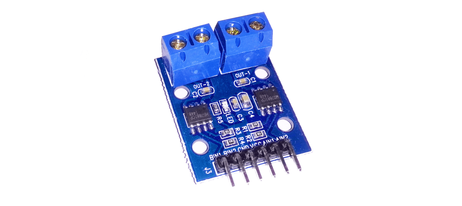
How to use H-bridge HG7881 (HG7881CP) module with external power supply and Arduino UNO
First-time use of H-bridge HG7881 (HG7881CP) module was pretty confusing for me. I didn’t find good (if any?) information about wiring this module up and running it with Arduino. But same time it seems to be quite popular. Here I share how I connected it to an external 12V power supply. You can use any other voltage between ~5V – 12V. Lower voltages might have some problems discussed in this thread.
This module can regulate speed (voltage) and direction (polarity). My example code demonstrates both actions.
Wiring H-bridge HG7881 and code example
Since this is a 2-channel module, we can operate two different motors with it. To obtain a better overview, I only use one channel (motor) in this wiring schema and example code.
| HG7881CP | Arduino / Power supply |
|---|---|
| GND | Power supply GND |
| VCC | Power supply +12V |
| A-1A | Arduino digital D8 (motor direction) |
| A-1B | Arduino digital D9 (motor speed) |
Arduino GND must also be connected to the power supply GND terminal. I think it’s a good idea to add also a resistor between power supply GND and Arduino GND (to limit possible over-current). You can read about this problem from this forum thread.
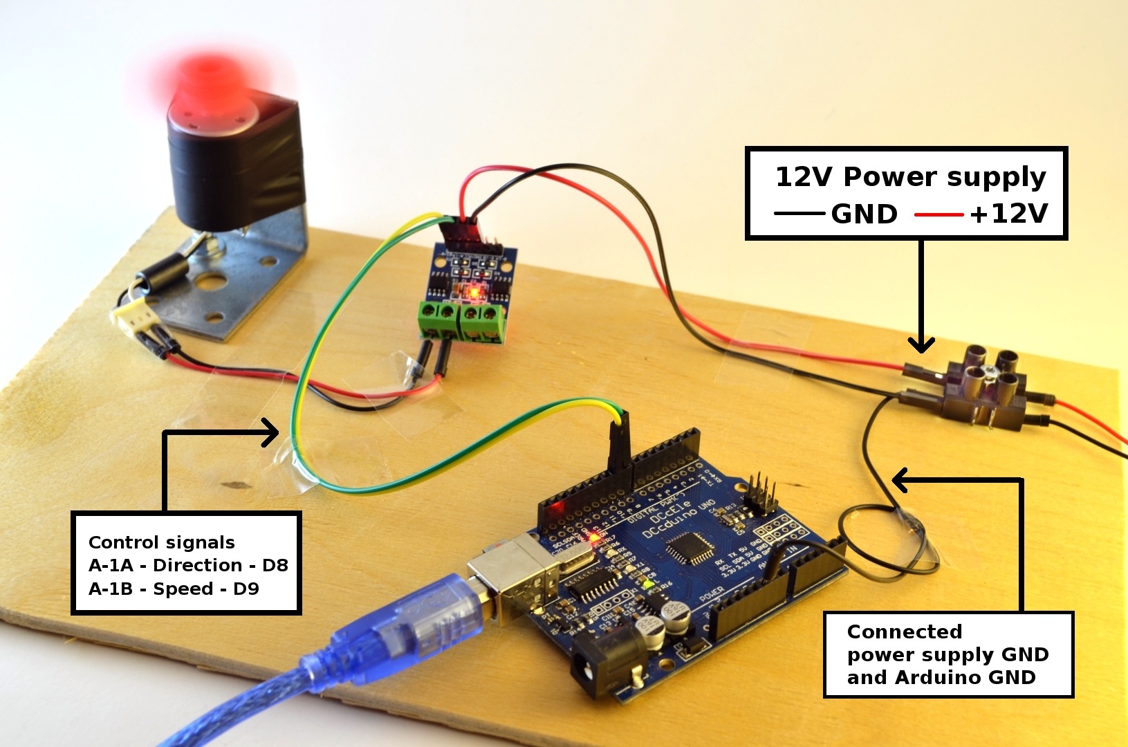
H-bridge HG7881CP testing with 12v power supply
A closer look at the wiring at HG7881 module side.
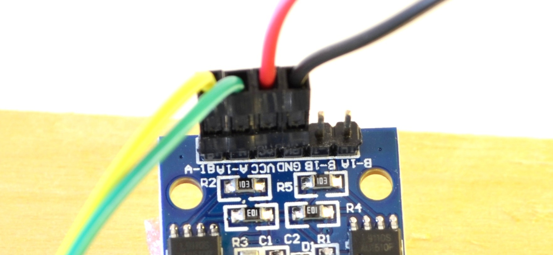
H-bridge HG7881CP test wiring, a closer look
Now you can upload example code to Arduino. If everything is wired up correctly motor should start spinning in both directions with a 3-second pause between direction switch. Same time increasing speed from min to max speed (0V to power supply voltage) for both directions. Note that there is inverting of speed value at other direction. This is Arduino sketch file I used.
Increasing speed doesn’t necessarily need to start from 0 or 225. You have to find your own sweet spot where the motor minimum voltage is reached which makes it running.
/**
 * H-bridge module HG7881CP/HG7881CP example code
 * http://diyprojects.eu/how-to-use-h-bridge-hg7881-with-external-power-supply-and-arduino
 */

/**
 * Create variables to be used to run motor A
 */
int motorAPin_A = 8; //Arduino digital 8 is connected to HG7881's A-1A terminal
int motorAPin_B = 9; //Arduino digital 9 is connected to HG7881's A-1B terminal


void setup(){
  /**
   * When program starts set Arduino pinmode for 8 and 9 digital to be OUTPUT
   * so we can use analogWrite to output values from 0 to 255 (0-5V) (PWM)
   */
  pinMode(motorAPin_A, OUTPUT); //direction
  pinMode(motorAPin_B, OUTPUT); //speed
}

void loop() {
  //set motor direction to "X"
  analogWrite(motorAPin_A, LOW);

  //start motor and increase speed while spinnning to direction "X"
  for(int i=0; i<=255; i++){
    //motor speed increases while we loop trough
    //values from 0 to 255 (0V to power supply max voltage)
    analogWrite(motorAPin_B, i);
    delay(40);
  }

  //wait 3 seconds while motor is running full speed
  delay( 3000 );

  //take 1 second pause, cutting power from motor ( speed pint to 0V )
  //so motor can stop (maybe your motor needs more time to spin down)
  analogWrite(motorAPin_A, LOW);
  analogWrite(motorAPin_B, LOW);
  delay(1000);


  //now we switch direction to "Y" by setting 5V to
  //direction pin A-1A
  analogWrite(motorAPin_A, 255);


  //start motor and increase speed while spinnning to direction "Y"
  for(int i=0; i<=255; i++){
    //To speed up like we did in direction "X" this module needs
    //inverting of value we set on speed pin.
    //So we go trough loop like before, but this time speed value
    //decreases from 255 to 0 (via inverting value)
    analogWrite(motorAPin_B, invertOurValue( i ) );
    delay(40);
  }

  //wait 3 seconds while motor is running full speed
  delay( 3000 );

  //take 1 second pause, cutting power from motor ( speed pint to 0V )
  analogWrite(motorAPin_A, LOW);
  analogWrite(motorAPin_B, LOW);
  delay(1000);

  //and now back to top
}


int invertOurValue(int input) {
  return 255 - input;
}
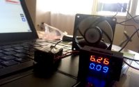
The result of running this example code
Following video demonstrates how this example code should run the motor. Note that whining at the start- it’s generated by PWM signal and if the voltage is too low, it won’t start. Just whines. Every motor has it’s own minimum operating voltage so they can behave differently.

You really made my day.
Thanks for such a wonderful tutorial and well commented code 🙂
Thank you for the write up and the pictures.
when setting up this circuit, i have to always give the shaft a small twist to get it to start turning, otherwise the motor only emits a high pitch whine. I have a 9v DC motor, and am driving it by a nodeMCU… any ideas why the circuit cannot ever start the shaft to turn by itself?
i can confirm that the wiring is all working right, and when the shaft starts turning, it speeds up, runs, stops and reverses. it just cannot start by itself 🙁
thanks!
From video you can see that little motor didn’t also immediately start running. Made also (PWM voltage regulation related) whine. I guess every motor has it’s “minimal voltage” when it starts to turn. This code starts from increasing voltage from 0V, but in actual applications you would need to find the sweet spot where motors starts turning (what voltage). But you said always needs manual turning. That is interesting. Even with maximum speed (voltage)? Unfortunately I can’t recommend anything at moment.
figured it out, the range for the node mcu is 1024 for analog output, setting it to the max of “255” is only 25%
Hello.
I’ve got into a problem using l9110. I’ve expected to use this driver for 12volt motorised ball valves, but came into a problem: when the voltage is above 5,5V , control input shorted to ground and no load connected, l9110 start to use about 70mA current per channel without any reason. Chip heats up, but doesnt fail. With lower voltages everything is fine, the board consumes 20mA, no matter logic input is high or low. All 5 drivers I’ve bought behave in the same way. Is there a faulty chips or a normal behaviour of that chip?
Experiencing the same on a HG7881 version of this same module; after some minutes LED on the module starts flashing and heats up badly… did you find a solution?
How did you wired it up? What was the power supply, what controller, what motors. Many questions here. Maybe faulty module?
Hello ,
Point1 :
I am referring to below bit from the code…..
//now we switch direction to “Y” by setting 5V to
//direction pin A-1A
analogWrite(motorAPin_A, 255);
Why we are using analogWrite for non pwm pin like 8 ?
When I try to use analogWrite(motorAPin_A, HIGH); — the program is not working?
Point 2 :
I am referring to following bit from the code,
analogWrite(motorAPin_B, invertOurValue( i ) );
Here the PinB value start decreasing from 255 to 0 — how this decrease in PWM duty can increase the voltage to speed it up?
So please help me to clarify above two points . thank you
Thank you for questions.
1. Indeed- can’t remember why, but it should also work with digital write also like you mentioned since it’s only switching direction (0, 5V). But when you used digitalWrite- did it work for you?
2. I am not sure why, but my board worked like this. I had to invert value to make it move like intended.
ist ein LOGIKMODUL habe einen beitrag gefunden für volle geschwindigkeit vor und zurück brauchte es für einen anderen zweck
https://www.bananarobotics.com/shop/How-to-use-the-HG7881-(L9110)-Dual-Channel-Motor-Driver-Module
int motoriA = 9; //A-1A Terminal verbunden
int motoriB = 8; //A-1B Terminal verbunden
void setup() {
pinMode(motoriA, OUTPUT);
pinMode(motoriB, OUTPUT);
}
void loop() {
digitalWrite(motoriA, HIGH); // NACH VORNE
analogWrite(motoriB, 0);
delay(3000);
// Motor aus
digitalWrite(motoriA, LOW); //LOGIK AUS
analogWrite(motoriB, 0);
delay(3000); // 3 Sekunden warten
digitalWrite(motoriA, LOW); //NACH HINTEN
analogWrite(motoriB, 255);
delay(3000);
// Motor aus
digitalWrite(motoriA, LOW); //LOGIK AUS
analogWrite(motoriB, 0);
delay(3000);
}