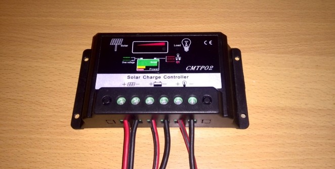
CMTP02 – disassembling this solar charge controller
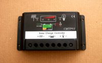
I want to share inside look at cheap Chinese solar charge controller CMTP02 (CMTP-02). I have a 30A (charging current) variant, but it has also 5A, 10A, 15A, 20A versions. It should be a PWM controller. Maybe even not that (like Didier pointed out in the comments section). I have not learned all the terminology regarding solar controllers and how to identify their type. But one thing is sure- MPPT should have DC to DC converter inside it (am I right?).
Some eBay users sometimes put MPPT int the title – but it’s misleading. It’s not that kind of charger. I thought also that it is but was bit disappointed (didn’t do my homework before buying it). Well- the price should ring bells if nothing else does. Anyway- I hope this post helps other people to choose their controller when stumbled upon this cheap charger. And get some inside info before considering to buy it.
Please note this post is written in the year 2014 and it’s possibly not that accurate anymore. They probably have changed their design also by now. But the basic concept is most likely the same. I If anyone can confirm please feel free to comment.
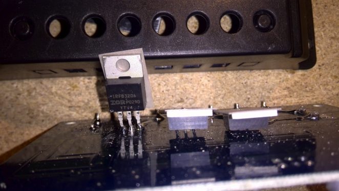
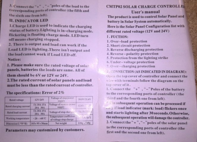
There is also pictures of 5-ampere version posted by Didier. You can look at them here. Also one user manual (10A version I suppose). It uses irfb3206 mosfets to do the heavy lifting as seen on photos.
How CMTP02 works?
If you are looking how this charger actually works you are in luck. Alan reverse engineered a 20A variant’s circuit and operation. You can read more info from his comment below from his website.
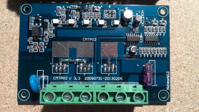
What is inside of CMTP02
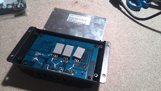
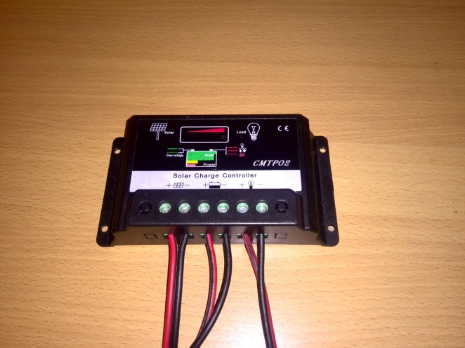
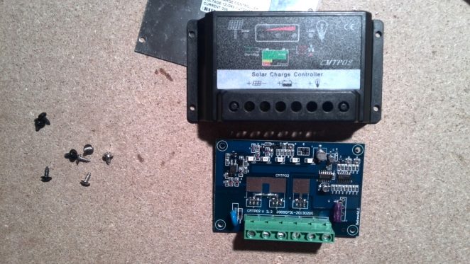
Well, check out these photos. I just opened it up and made some shots to overview it’s content.
Here you can see that mosfets are heatsinked to the backside (but not firmly). Just little contact with pressure. Someone who has used it with higher loads can comment- is it enough and how well it works.
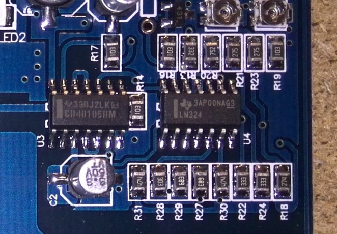
A closer look at chips on board. Probably controlling? I didn’t look up their datasheets.
Here we can see what kind of mosfets are used to drive current. All three was the same (if I remember correctly)
And finally- picture of manual. Just in case.
I’m writing from Hungary. I bought a new battery to 9Ah end 3 led its red from batteri controll!!
Input led its( reed) led 1 out led its (red) led2
(INput 40w solar penel)
led 3-4-5 its (red) its ok?
what should that be orange led end green led?
thank you Gabor
I don’t understand what you are asking. The LED’s on cmtp02 just indicates battery level/voltage. If all 3 LED’s are bright RED – your battery is good.
Hi, just to tell you that the link for basic info on CMTP02 is broken.
I’m currently testing this solar charge controller, i’m not really convinced for now.
Hi,
thank you for broken link info. I have only tested it on low amperage. Around 2-3 amps. Did what it says but I have no continuous working tests made on some real system.
Thanks bro,
Have you figured out which are the charging steps with this controller ?
It seems to me, comparing it with several other models, that it stays too long on 14.4V.
Do you know what it means when the “solar” led is flickering in greeen ?
Many thanks,
Have a nice day !
I have a 5 Amp version of this controller. I have 3, actually. And, I have three very small solar panels, about the size of a 4 slice toaster. Not sure what the rating is, but am sure it is under 5 Amps. I use the three to charge up two ATVs and a Suburban. The issue is the Suburban is not being charged, It is a honker of a battery, where the ATVs are smaller. What I am seeing on the Suburban is NO Load Light, where, on the ATVs I do see the Load light. If I swap out the systems, I get the same results on the Suburban with the different System, and the same results on the ATVs with a different system. System means different set of panel/controller. Same means the load light is always off on the suburban no matter which panel/controller I use, and always on on the ATVs no matter which panel/controller I sue. What is up with that?
Is it possible that Suburban has battery which needs more voltage to be loaded. I don’t know your panel voltage, but I would assume that it must be greater than ATV’s battery needs but not enoygh to load Suburban. As if solar panel which is rated 6 volts (actual output is over 6 ) can load 6 volt battery (6 volt battery charged should be 7.2V)- but when you hook it up to a 12V battery- it would not charge at all because of voltage is not over battery voltage.
This is not actual MPPT charger so it needs input voltage to be over battery voltage to be in charging mode.
I looked up the specs, 24 DC/AC volts, 1.5 watts, it measures 13.75 x 4.75 (not that that matters). I think it must have something to do with the battery discharging faster than it is charging, but, that does not explain why the Load light is not lit on any of the three solar/controller systems. I am new to all this, so I may be missing something.
Update. Since I wrote the first post, and before I went and looked at the controller just now, I charged the battery all the way up. The Load light is lit, but the three red lights are now down to 1. So it is loosing charge faster than it is being charged. I do not drive this Suburban much. It sits for months. I had hoped that this would keep the thing charged, but, apparently there is a drain larger than 1.5 watts coming from somewhere. Nothing is plugged into the cigarette lighter socket. But there is a car alarm. Unless someone were holding down one of the FOB buttons for the Alarm, I would not think it would draw that much current. Not sure how to measure the current loss with no solar attached.
Haven’t found a schematic yet, but it is safe to assume the CMPT02 is powered by the battery (to constantly check for ‘low voltage’ condition), and is drawing more energy than your solar panel can deliver (1.5W / 24V = 63mA).
To keep the suburban charged, forget about the charger and connect the panel directly to the battery (via a fuse).
The solar panel itself is made of diodes, but if it makes you feel better you can connect a diode in series to prevent the battery draining via the panel.
Hi.I by this controler cmtp02 30A.When the batery is conected with controler red light is on(overlow).the voltage on batery is 12.9v,and it is a full charged.I disconected for a 30min,and conected again and it is a same.What can be a problem.thank’s.
Today was sunny and i tested regulator.he was charging batery antill 15.4v,and then solar lamp start flashing and Normal and full lamp was lighting.Is there a way to adjust voltage 1.5v -.
my PHOCOS has microprossesoe (PIC16F676), this has only op amps. Is it real PWM?
Hello,
Ce module CMPT02 n’est pas un système MPPT. Il m’a détruit mes deux batteries de 6AH par surtension. Il ne contient qu’un système de comparateur de tension avec 4 AOP !
la référence “20A MPPT Solar Panel Battery Regulator Charge Controller 12V 24V Auto Switch TLS” sur Ebay est trompeuse.
Your PHOCOS with PIC16F676 is a CML05, CML08, CML10, CML15 or CML20 series ?
Thanks
If you remove R20 and short circuit R21,you can adjust output voltage by W2. It is necessary for NiCd batteries.
hi. i`m using this mppt.
but i don`t know why load LED didn`t lighting.
please tell me reason.
thanks.
Was load connected and working and same time?
no.
connected LI-PO battery and connected speed controller(RC-plane, load) to mppt.
but didn`t load lighting and speed controller is no working.
(didn`t connected solar cell)
so i can`t working same time.
i`m connected battery and speed controller line about load to mppt.
so load is lighting and controller is working.
but i want charging battery on solar cell and working RC-plane same time.
I’m sorry my English ability.
yes.
connected LI-PO battery and load ( RC-plane speed controller) same time.
but didn`t load lighting and speed controller is no working.
(didn`t connected solar cell)
I’m sorry my English ability.
yes.
connected LI-PO battery and load (RC-Plane speed controller) same time.
but didn`t lighting of load and speed controller is not work.
(didn`t connected solar cell)
i`m sorry my english ability.
Thanks, almost bought one thinking it was MPPT.
Hi,
I got 2 of the 5A types and just opened one of them. Before even taking out the pcb, I freaked when I saw it looked like no parts had been soldered on it, so I feared I was sold blank pcbs. Anyway, after popping the pcb out of the case, the other side was populated, but not completely.
I haven’t tested it yet, so I don’t know if it works.
I assume the parts missing are for some extra features or perhaps different configurations for other current handling. This is a 5A, and maybe that same pcb is used for other versions.
However that pcb from this 5A version doesn’t look quite like this 30A one posted here, so at some point something changes when going up in current handling.
On the photo posted here about the “controller chips”, there is an LM324 which is a quad comparator chip, and the other seems to be a CD4010, which is a cmos hex buffer. Certainly not any kind of controller. I suspect this thing is far simpler than it is boasted to be, and I even have doubts that it is actually pwm. Only 2 chips, which aren’t controllers or anything complex, and all the rest is basic passive and active smt, which seems to be analog to me. Anything pwm would be a little more complex. Maybe I’m not looking at it close enough, but at first glance, I have serious doubts.
Would anyone have found any schematics for this?
Thank you for this info! I updated my post a bit, regarding to your info. Maybe I am wrong when I say it’s a PWM. I have not learned all the terminology regarding solar controllers and how to identify their type. Added disclaimer into the original post.
PWM would mean there is some kind of “clock” running, likely with some crystal based oscillator to drive it or some type of logic to chop up a dc level to make it a square wave of some kind. The PWM term just means pulse width modulation, and that means there are square waves being generated, with their duty cycle altered as needed. This alteration of the duty cycle is that “modulation” of the “pulse width”.
It might be pwm, and it is being marketed as such, so you make no mistake on your end, that’s what it’s being sold as. It’s just that its apparent simplicity in its electronics and the absence of some commonly found things in such type of circuits that makes me wonder and question that fact.
Maybe I missed something, that’s quite possible, but from what I see so far, it’s hard to believe it is pwm.
I can take photos of what I have and send that. This could also be a good addition to the posting, with a real variant on that model. I have one apart right now, so it’s no stretch to take a few photos.
I can’t post attachments on this reply, so I don’t know how to do this or where I would send the photos.
I also just scanned the manual that came with it, and it looks a little different from the one you posted. Let’s share all this, so people can make informed choices and eventually enough sharing may allow some who are having issues to try to fix them.
I bought a CMTP02-5A in the beginning of 2015. It looks exactly like your 30A version. I recently got a free 260W 36V panel that was inop and was able to repair it. I was wondering what was similar and what was different between the various amperage controller hoping to be able to upgrade my 5A unit. Looks like the only thing that’s different is the FETs. I’ll replace the unmarked FETs in my 5A unit with the 3206 FETs and try it out. As for it being a PWM all it takes in a feedback circuit using the hex buffer and the comparator. It’s much more crude than a xtal controlled oscillator, but it works. Thanks for the post. It helped me out quite a bit.
I did a little more research into the controlling components inside this controller. The CD40106B is a Schmidt trigger which is used for the oscillation of the pulse width and the LM324 is an op amp used for controlling the transistors and FETs. After looking at the time and cost of adding new FETs to the 5A controller I decided to buy a second gen 30A PWM from eBay for $9 USD. Hope this helps.
hi,,,,
The charge controller is a circuit schematic for me, please
??
email: majid.bagheri.1987@gmail.com
https://www.mikrocontroller.net/topic/371582#new
Just hooked up my cmtpo2 to a 136 watt flexible solar panel and all three lights are blinking red, is that bad or good? From what I can tell from reason it, it’s overloading too much power into it but not sure.
From reading* the diagram on the charge controller.
Got a 20 amp one was OK (13 volts) NOW full 33 volts coming through what part do I fix ? Cheers Jak
Is it a dc-dc converter for the solar input? All it says in the manual is the max solar input.
I have checked a lot of these on ebay and nowhere does it specify the range for the solar input.
As said in article and talked about in comments- it’s not a DC-DC converter (MPPT). Input amps differ by model.
I have the 10 amp module. If I connect the solar cell 20watt the Solar light goes green but nothing else lights. Without the battery connected I measured the voltage across the battery points on the controller and it measured 4.6 volts the output measured 2.7 volts, the 5 volt measured 0.7 volts.
Does it need a battery to function correctly. When I connect the battery the battery and load lights go Green and the voltage measured on the out puts were 5 and 12 volts, what I can not tell is if the battery will get charged as it is fully charged at present. I will update when the load has been on for a period of time. Anyone know if it is working correctly ?
For anybody reading this, NEVER connect your panels before the battery.
Connect battery to charger first (and that goes for any charger). Then connect load and/or solar panels to charger.
There’s reasons for this. To take down or service your system, remove panels and load first and battery last.
The latest version (15/7/16) does not have all the presets shown in the photos. The circuit diagram on the mikrcontroller web site refers to this latest version. The unit I have was regulating at too high a voltage. To bring the voltage down I put a 500k preset in parallel with R24 (333) and waited until the unit started to regulate and adjusted the preset to give the desired voltage. There is plenty of room for the preset inside the unit, I put it just below R24 towards the laod fuse.
Pin 13 on the quad opamp LM324 is set to 2.5 by the voltage reference. At the start of regulation pin 12 from the voltage divider including R24 should also be at 2.5V.
I have a CMTP02-30A solar charge controller.
When I connect it to a 24Volts battery (I.e., 2 Nos 12Volts 100AH batteries), the load light comes on green, and the battery light, all the 3 leds, comes on red in full. I discharge the battery completely until the inverter goes off by itself yet the 3 leds remains on but the solar panel indicator light does not come on.
Please advise on what could be wrong and the way out to solve this problem.
I don’t know how to debug this. But yes. Panel indicator light should come on if you connect it.
I recently bought CMPT02 controller. I wired it as per instructions. but my unit is not showing Normal.It is showing overlow.I charged the batteries to full with electric through inverter but the Normal is not working. My 4th led is also not working. I connected 2*90Ah batteries with a 150w 12v spv as charging source. I connected inverter directly to the batteries because i sometimes charge by electrical source. What is the problem?charge controller faulty?I bought it online on 09/12/2016.Pl help!!!
Hard to say. Maybe it’s broken if wired up correctly . I can’t help or suggest anything to help you.
I also have the cmpt02, i connected a brand new 80a/h battery to my charge controller and only 2 red lights came on out of 3, i connected my 2x60watt panels in parallel to keep it a 12v system and connected my load which is a 2.4amp bilge pump and my battery lasted 2 days and my load turned off can anyone help me out, is it my charge controller or is my battery to small for my load or panels not enough? Its an aquaponics set up
I’ve got a couple of these controllers. I’ve also got a couple of anothe variety.
My observations…
1. They go bonkers when set to charge two separate batteries from the same solar panel.
2. Vmin is way too low 10.5v
3. Vmax is too high 14.2v
Sharing a common battery negative and powered device negative makes them go bonkers.
The voltage supplied is not corrected and declines with battery voltage.
It’s cheap but you’d be better off with another solution. Quite what that is, I’m not sure because I’ve not seen any charge controllers genuinely designed and built outside of China. Usually it’s the same circuit repackaged.
I brought this 5A controller 2016 and have same problem and I do not know the answer. I have on it 12V, 5W solar panel, 12 V, 2,5A battery and couple of led’s with power of 1W or 2 W. The problem is that in manual say when the battery is completely charged all led’s is green. I change 3 battery with current same or smaller but led’s on ‘charge’ is all three led’s red never green. Second, I never unplugged the battery or solar over night and if battery led’s is all red without the sun, the load not working and until morning the battery is completely drained. I do not see the conclusion but see a similar problem with you. Do you have answer what can I do? Or is it better do not buy chip conttroler.
Thank you.
I bought 10A CMPT02 controller. The cutoff voltage was too high so I traced the circuit and published it on my website. The link is http://www.cashin.net/CMTP02/CMTP02_solar_controller_circuit.htm
The so called manual that came with it is all rubbish. It is not an MPPT controller, there are no colour changing LEDs, and if you blow the load fuse, it stays blown. Note that all the +ve terminals are common, so any connection between panel, battery, load on the -ve side will cause problems. They must be isolated. I am still working on it.
Thank you for insight and sharing your web about circuit of one of these models.
Hey Alan,
Can you update the link to your site with the scematic to the cmpt02 charger?
Thanks
I have a question if my solar panel is 48 volts and my battery bank is 24 volts can I use the solar controller which is a 30 amp controller model number cmtp02.
I have done testing with a 12V 35W panel and several 12V car batteries. The manual is very misleading so here is a guide:
The 5 LEDs on my model are panel (green) charge (3 red) and load (green)
First connect a battery to the battery terminals. Unless the battery is flat (below about 9.5V), or connected the wrong way round, at least one charge (red) LED should light and the solar panel can be connected. If there is no light, something needs fixing. The controller may not work because it needs some power from the battery. For a battery with some charge (above about 11.5V) there will be two charge (red) LEDs lit and the load (green) light should also light.
Connect a solar panel. Important, make sure there is no connection between the battery -ve and the panel -ve. If the solar panel is working (has light on it), the panel (green) LED will light. If the LED does not light, either there is something wrong or the battery is overcharged and all 3 charge (red) LEDs will be lit.
Connect any load. Again, make sure there is no connection between any of the -ve terminals. If the load (green) LED is lit, the load should be getting power. If the load LED is not lit, the battery is nearly flat.
Although the panel (green) light is lit, it does not mean the battery is being charged. Charging only happens when the panel voltage is greater than the battery voltage. There is no indicator for this. However if the battery is charging, the red (charge) LEDs will slowly get brighter, the 3rd LED comes on above 13V and the LEDs get much brighter as the voltage rises. When the battery is at full voltage, the panel light will flicker. At first it is mainly on but flickers off, this gets faster until it flickers continuously, then it is mainly off but flickers on.
Notes:
(1) The load circuit is protected by a fuse soldered onto the circuit board. It will be difficult to replace, so make sure the load is within the rating of the board (mine has a 15A fuse to protect a 10A circuit).
(2) Wiring to the battery should be short and thick, and the battery should have low internal resistance. The circuit is not as effective if there is substantial resistance. If the load circuit detects a low battery voltage, it should switch off the load. If there is too much resistance, removing the load causes battery voltage to rise causing the load circuit to switch on again. This causes rapid switching of the load which is not good for it or the controller.
(3) This charger has no program, it charges to a fixed voltage and holds the battery at that voltage. The voltage limit is above 14V which is high enough to cause gassing in lead acid batteries. Some batteries are designed so this is handled, a battery with liquid electrolyte will need water checked and added at regular intervals. My opinion is this is unsatisfactory unless the panel is a small one (say 5W) charging a large battery. The final voltage can be lowered by modifying the circuit (adding a resistor in parallel with one on the circuit board). For my particular board (and there are many variants), a 470K resistor in parallel with R22 lowered the final voltage to 13.7V. Ideally there should be temperature compensation of approx -20mV (for a 12V battery) per degree C. But we get what we pay for. Apart from this limitation, the circuit is well designed and does what it is designed to do.
I made a mistake. The resistor to parallel is R24, not R22.