How to wire digital dual display volt- and ammeter
Once I bought a popular “Chinese” volt- and ammeter gauge with 100V/10A ratings. Unfortunately, I didn’t find any good resource about how to wire/connect it. Actually, it’s not rocket science, but I had waited for it 2-3 weeks and didn’t want to blow it at first try. All the diagrams were somehow too technical for me.
The original article included only one variant of these digital volt- and ammeters. Now I have included three most common variants of them. If you order digital 100V/10A volt- and ammeter gauge from China or other markets – it’s most likely one of the following.
They all have a bit different wire colors. I will cover wiring for all of them in this post.
These meters are good when you want to measure current and voltage at the same time. A feature that usual multimeters lack. For example, I have used it to measure the output of my DIY solar panel. They are inexpensive and easy to connect.
How do these ammeters work?
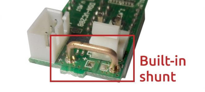
These meters calculate current flow by the voltage drop across the shunt resistor. They have built-in shunts that should withstand measuring as much as 10 amperes. You must see shunt behind your volt- and ammeter. That small bridge bent from a thick wire on PCB.
Important! If there is none- this guide is not for you. You need a wiring diagram with an external shunt instead. Also when measuring current that exceeds 10A which can be handled with the internal one.
Wiring basics
They are basically the same. There is a connector with thick wires and connector with thin wires. But coloring of wires vary. Amperage measurement is done by passing power through thick wires. Power to the meter itself is fed through thin wires.
They all can be wired such way that you don’t need a separate power supply for the electronics part. You can use the same power supply where your measured load gets electricity. But then you can only use a maximum of 30V since it’s the maximum operating voltage for the meter itself. Also, you can’t measure voltages below 4.5V. If using the same power supply you even can leave thin black wire un-connected since they have common ground/GND.
Reversing polarity on these meters?
You can’t reverse polarity on these meters when measuring amperages (probably voltage also). I tried this on the first one in the list. It shorted out. It’s probably because of the common ground and by reversing you are feeding positive voltage into GND connection. If someone has some other info please let me know.
Also important! You CAN’T read current in the reverse direction with these ammeters.
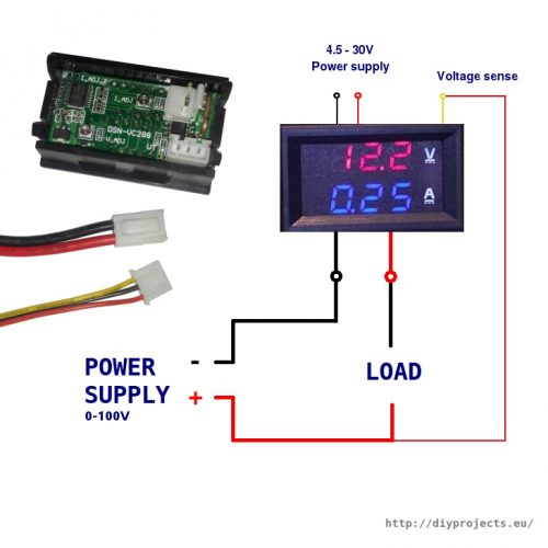
Wiring of dsn-vc288 with thick red and black wires + thin yellow, black and red
Wiring dsn-vc288 makes the most sense to me and seems to be most popular also. It also has clearly marked model name on the PCB which makes it easy to identify.
Red, black and blue thick wires + thin black and red
This exact one was in my original article. I guess it’s not popular anymore because can’t find any offers for these.
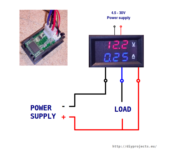
Red, black and yellow thick wires + red and black thin wires
Seems that dsn-vc288 has take over the market since I can’t find any offers for this version also.
Important! I have not tested this one myself. If someone can confirm this is correct I would be very thankful. From the info I found from sellers and one youtube video- this one has a bit tricky coloring. The voltage sense line is also a thick wire and it’s not yellow. It’s a red one instead!
Can someone please confirm this schematic is correct?
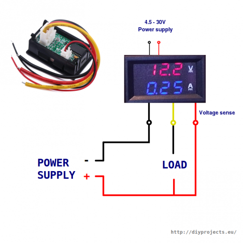
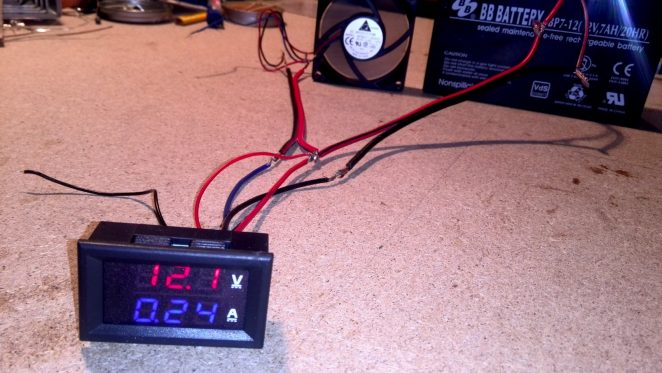
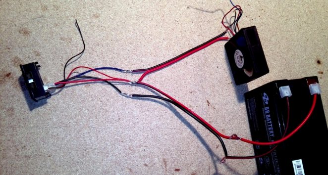
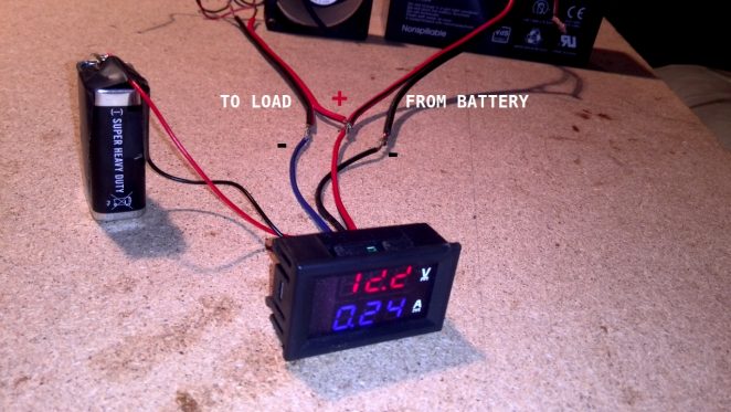
Here are some photos of testing them
One test with the external power supply

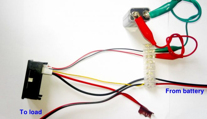
Hi.
When there’s no voltage on the blue wire to the load what would be the cause?
Is it a faulty amp/volt meter?
Nice tutorial mate.
Regards,
Albert
I don’t fully understand your question. Do you have load connected between + side and ammeter’s blue line? Have you same kind of volt-ammeter?
It’s like the ground (black wire) goes “through” ammeter and + is connected directly.
Full morning trying trying, result headache. Google to your website and bingo !!
Thanks a lot !!
Hi.
That is correct.
I have an amp/volt meter just like the one you have in this tutorial.
The way I had it setup for the past 3 weeks was thinner two wires, Red & Black to my 22ah battery. The thicker Red, Black & Blue are connected the following way;
Red is connected to the source “12V Battery”.
Black is connected to the source “12V Battery”.
Blue is connected to the load “Charge Controller”.
It all worked fine till now but it’s gone bust. There is no longer voltage on the Blue wire.
Any advice truly appreciated mate.
Thanks.
Albert
I am still wondering why the black thick cable “negative” is serving the amp meter!
I always thought the amp meter should be on the live cable in series with the load? In this case is in series still but on the negative side?!
It is now working mate. I was using RED with RED and BLACK to Black with the BLUE serving the load as negative.
Sorry, my mistake.
Thanks for taking an interest and trying to help.
Regards,
Albert.
It really doesn’t matter. Look up Kirchoff’s law and it will all make sense. They just use the negative because it makes it easier to design a circuit that works.
Excellent tutorial, with pictures that help in understanding. I’m going to buy an ammetr/voltmeter and I have the same questions as yours, when you started.
Thank you very much for providing such useful information.
Good to hear.
But keep in mind. If shunt is not built in, this diagram would be invalid and missing a shunt. Mentioning it just in case.
Janar,
Yes, the instrument I’ll buy has a build-in shunt, as you mention in the second sentence of your article.
Again, thank you very much for the detailed article and the fine clarification.
Hi Janar,
My ammetr/voltmeter arrived and yesterday I wired it according to your directions.
It works like a charm!
Thank you very much, once again!
Great tutorial. One question in the picture labeled “Volt ammeter with external power supply” is the meter connected to both the external power supply as well as the main batter? Thanks
Yes, both. That shold show that you can use this with external power supply (since power supply must not be over 30V but measuring range is much bigger)
My dual digital voltameter has red, black and green thick wires (not the thin red and black to power the display). Chinese supplier unable to provide any advice or technical data. Red connects to terminal on the display labelled “Vi+”, black to “COM” and green to “I+”, but I have no idea what these mean and they don’t match the incorrect wiring diagram shown on the suppliers ebay page which refers to thick red and black and thin yellow wires. The display should obviously be in series with the load, but between which two terminals should the load be connected? The third thick wire is obviously used to measure battery voltage of the circuit, but which wire should this be?
Do you know if the ammeter can read both positive and negative current. We wish to use this on an RV coach battery and will have battery “drain” and “recharge” currents, obviously in opposite directions at different times.
I am pretty sure it only can measure one way. I would have to test this, but probably not. There is no place for minus sign anyway on the display.
Hi Janar,
I am about to improve my 50V / 6A bench power supply with a similar meter. What I don’t understand: is the current shunt built into the meter? As the one I am about to buy is specified to 100V and 10A it seems unbelievable. I mean, the amperage. Even the wire cross section looks too small for that, let alone the miniature connector the wires connected to. My seller offers 4 other versions of the meter with different configurations, color, etc. , among those two with 50A and 100A limits. I’d expect a separate current shunt for such amperage, but also for 10A. I could not see anything like that on your drawing, neither my seller speaks about, so I am confused.
Thanks, Laszlo (Budapest, Hungary)
Hi Janar,
Thank you for posting the wiring diagram; I need it! I just received one of these fellahs. Purpose is to measure DC volts supplied to my model rail track. It would be nice to get a reading of amps supplied too. I connected up as per your diagram. In my situation the power supply and the load to be read are one and the same, ie the 2 rails of the track. I get a correct volts reading, but the amps reading is 0.000, even when a train is running. Any suggestions please?
When you say “Black wire (ground) is not needed. “, doesn’t that mean that the current is sinking through the small black wire that drives its circuitry? I’m sure that’s fine at small loads, but I can’t imagine that would be good when you get into the amps.
That was comment about powering chip/volt- and ammeter itself. No current is flowing trough there.
Looks good, but mine came with different wire colors. Small red and black, then blue (nearest the smaller wires), green then yellow. I found different sources with different answers. Looking at your pictures, my blue would be your large red aka positive polarity, but I cannot see the placement of the other 2.
I saw one place that said green was voltage detection but when I tried on a battery it sparked and meter went dark. Just to make sure I used just red and black and seems to still work ok, so this is just a pain.
Hi Janar,
I have the same V/A meter which is to be installed to the 12V battery charger. Could you explain how connect all five cables?
Hi! I bought to of this meters and none are working, I made the connections like your pics . I saw two little bolts in the back, do you adjust this bolts before turn on your volt/amp meter?
Thanks in advance!
Are you sure they were exactly the same ones as seen on my I photos? If not- I would better not try before knowing right connections for you version.
No need for messing with potentiometer in back.
sir,
i want to read my 70 Amp DC battery Ampere
How can i do this…?
i don’t want to read the load ampere
i just wan to read the rest ampere left in my battery
LIKE new UPS….(They Show How much percentage battery is left)
BATTERY AMPERE….
MY Battery is DC-12 V 70Amp
Sorry. Wrong place to ask this. I don’t know.
It works great as shown on the picture with computer cooling fan, thanks !
Now if I replace cooling fan with solar panel and no change at all on the wiring, will it work ?
Wait- you are testing this with cooling fan right? If yes- cooling fan is the “LOAD” part and you can’t just put solar panel as the “LOAD”. This meter runs only one way.
But I assume you will use this right. Connect solar panel to the “Power Supply” part and you are fine to go if voltammeter is the same as in my photos.
Simplify this for me please.
I have… say a battery, any batter within the voltage range, and I want to do nothing but read that batteries volts and amps, nothing more.
We have 5 wires, 3 fat that are red blue and black and 2 skinny that are black and red.
So using that description of the wires and what I need, what wires go to positive and what wires go to negative?
It appears you have fat black to the neg pole and both red wires to pos. If that is the case just an agreement of that will be fine.
I got mine on ebay and it seems no seller there is bothering with a simple diagram on how to hook these or other 4 wire systems up. I guess I’m just amazed that didn’t cross their mind…if for no other reason that people will be saying it never worked and try to get a refund (and some of them do not work from the get go) after they blow it out, and they will get more sales if they just make this clear to people as well as more satisfied customers. Not to mention the combined time they could save people by taking just small mount of time to place one measly diagram on their listing. OK, rant over. 🙂
Thanks for taking the time to post this instructional.
Is it the same kind of meter as shown in my photo? At least wire colors match up.
Fat red goes directly to load / what ever you are running. And minu pole goes trough meter – fat black in and fat blue out.
Skinny red and black can be powered via external power supply ( this voltammeter has operating voltage DC 4.5 ~ 30V ). So if you are measuring voltages over 30V you should power this meter with external power with less than 30V.
t pretty much the same meter today (also waiting for several weeks :D) and at first, the wires looked a bit confusing. Thanks for this…wouldn’t have thought the thin wires are just a powHi! I goer supply to the unit. I have a similar one that reads only voltage and it doesn’t need any supply except for the measured input, so this was a bit odd.
Thanks
Stanley
This is concerning the voltmeter that doesn’t “need” any supply. I takes it supply from the measured source. Since the voltmeter circuitry needs a minimum of ~4.5Vto operate properly, this particular voltmeter cannot measure voltages lower than ~4.5V. Its uses is limited to voltage measurements in low impedance voltage sources (ex. batteries, power supplies)
Thankyou Janar! Finally a simple wiring diagram that works for these compared to some of the other crap posted elsewhere by electrical “experts”.
It worked for me, but I have a more complicated question. I am trying to wire two of these modules to a dual adjustable regulated power supply (those of the LM317 and LM337). How can I wire these kind of voltage/current meters?? The trouble begins because the positive of the negative part shares connection with the negative of the positive part (they have a common ground). Thanks for the potential help!!!!
Thanks for your wonderful tutorial.
I just got a couple of V&A meters with Blue Volts and Red Amps on the picture of the display. Supposed to measure up to 100 volts, and up to 10 amps. Part number on the circuit board looking at the back side says DSN-VC288, Looks like yours on the front, but on the back the wires are different. Actually the wires seem more sensible to me.
Wires:
1 triplet of 3 thin wires: Black, Red and Yellow.
1 pair of thick wires, Black and Red.
I presume the thick Black and Red wires are to be put in-line with a flowing current, Red wire to + source, and Black to – direction. Should measure flowing current 0 to 10 amps. That would mean that any shunt is internal, and probably the lower Red amps display actually is really measuring millivolts across a built in shunt, scaled to amps for display purposes.
I see shunts for sale on eBay are typically rated to yield 75 millivolts at the full amperage they are rated for. So for a max rating of 10 amps the shunt being used in this meter must have a resistance of .075 / 10 = .0075 ohms. I gather that means that the typical digital ammeters are actually mostly just 75 millivolt voltmeters scaled as necessary.
I made a quick test on opening the packet, using a 9V battery connected with the small black wire connected to negative side and the red one to the positive. That seemed to light up the display with top Blue display showing 00.0 and the Red lower one showing 0.02. Then the small Yellow wire, if I also connected it to the + battery terminal caused the top display to register 9.2 volts. So I guess the small black wire is the common ground, and then the small yellow wire is the voltage probe.
The 0.02 amp reading with nothing is connected, means I might have to use the amps trimmer pot on the accessible back side of the circuit board, to zero it, but maybe that’s just a bit of unconnected amp wires floating in the air effect. Will see about that later. I also see there is a volts trimmer there too, in case calibration drifts.
Am going to use it to measure the Voc and Isc of some solar panels I have. Later when in service with a grid tie micro-inverter I can look at the Vmpp and Impp as the sunlight changes angle or clouds roll in. Nice range for a meter intended to measure solar panels.
Instead of using the battery, in some circumstances I might just use the panel itself to provide power for the meter, but then I’d have use a voltage divider (two resistors) across the panel output, or something like a small 3 terminal voltage regulator chip and connect the meter power feed to that. Some panels I have only go to max 20 volts or so on Voc, but others go right on up to 50 volts (in summer) or even up to 55 volts (at 40 below zero in the winter). Would have to pick the right values po protection components to minimize the distortion to the accuracy of the reading, and still provide enough power for the meter. The specs say 20 mA draw, but max 30 volts, powering the meter before burnout. Wouldn’t be able to measure low voltages very well if I used the panel itself in place of a battery.
I’ll reply to my own posting here, if I learn that I have misunderstood something.
I don’t know if i’m in the right place to ask this question. I want to use a 24 vdc amp meter for my elect train layout, the problem I’m having is how to hook up the meter so I can reverse the polarity having the train run in reverse. I don’t need the meter to work in reverse. Can anyone help me or refer me to a site that can help me . Thank you Paul
I guess you can’t use these kinds of meters between power rails if there is polarity reverse in play. I just tested – at least “Red and black thick wires + thin yellow, black and red” version shorted out. It’s probably because they have common ground for measuring etc. So reversing power sends positive power into GND.
Maybe you should install meter somewhere between power outlet from the wall (I am guessing since I have no experiences with toy trains) and before unit that is responsible for reversing the current?
i wrongly shorted the shunt and current value was stuck at 13.5A.
I have resetted (jumping 2 pins on the PCB) and now it remains at 0.0..0.1A.
Does it mean that i have burned it? Can i replace the shunt resistor? Any hope to fix?
Volmeter works fine
Which meter do you have? I have not shorted mine so I am not sure. Shorted or reversed polarity?
i have Built-in shunt on volt- and ammeter-100V / 10A / DSN-VC288.
i think shorted, not reversed
I am still confused. I have a 100v/10A DSN-VC288. It has a small red, black, and yellow wire. It then has a large red and large black. I thought from your diagram I need to tie the yellow wire to the small red wire which goes to the positive battery/power source and then black goes to the battery/power source negative/ground. From my basic electronics the ammeter (large red and large black) would be in series with the load being measured but that is not quite what I am seeing in your pictures. Your picture shows 2 power sources (I think) in that you have the small red and small black going to a 9v battery and the small yellow in that bundle going to the power supply positive but the pictures is not clear. Also why do I need 2 power sources if I can use the same power source for both the load under test and the DVM (DSN-VC288?
Thank you.
1) Interesting. Seems that you see some other schema- I have tied small yellow one to the big red wire ( http://diyprojects.eu/wp-content/uploads/2018/09/wiring-10A-100V-digital-volt-ammeter-thick-black-red-thin-black-red-yellow-wires-500×500.png?ts=131 ) which measures the voltage on the system under the test/load side. Not to the small red wire.
2) You don’t need 2 power sources if the voltage is not exceeding much over 30V. But this meter is rated to measure up to 100V. For example – when measuring load in the 75V system you have to have a separate power source for the meter itself (small wires). 75V would fry the meter. I have mentioned that in “Wiring basics” paragraph. Maybe I have to make it more clear why separate power source for the meter.
I understood the max rating of the DVM in relation to the power source. I am wanting to insert this DVM into several power supplies, none or which exceed 30v, to measure both voltage and current. This picture
http://d3pjxncsu26pvf.cloudfront.net/wp-content/uploads/2014/03/volt-ammeter-testing-first-try-662×373.jpg
makes me think that both thin and fat red wires and thin yellow wire tie together and go to the power supply and the fat and thin black wires go to the power supply/source ground. Correct?
That image you linked is not meant to describe anything- it’s just a featured image for blog post demonstrating one of these meters working. Additionally- it’s not the same anyway (not DSN-VC288). As you can see I have included 3 different types of meters here.
***
But yes – you can wire them into one source power supply if voltages don’t exceed 30V as you described. Fat and thin red wires go together and also thin yellow wire. Then fat and thin black wires go also together. You actually can leave black small wire disconnected since they have common ground anyway.
I have second version (with blue wire) and I was unable to figure out how to connect it properly – for LED diode it always showed 0.00A instead of 0.02A (21mA). With your diagrams I verified my connection and finally found that load was simply too low. Meter has quite low accuracy, however it can be calibrated with two screws.
You really helped me – thank you!
Thank you for low current and accuracy comment. It’s a good point actually. I have used this more for higher current measurings and maybe that’s why I haven’t noticed it comment on it in the article.
Hello, thank you for this article.
When looking for this device, it isn’t very clear what the voltmeter displays when voltage is < 10V : merchant photos often shows 3 digits but some user photos shows only 2 digits.
Have you got a hint (or a reference) to choice a device which displays 3 digits for voltage < 10V ?
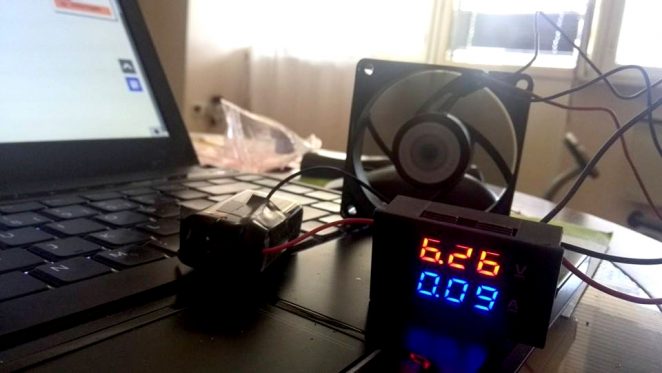
Hi. Not really sure now what you mean by 3 digits? Accuracy of 2 places after the comma? Like 6.26V – like on the thumbnail/header image of this post with a “Red, black and blue thick wires + thin black and red” one?
Unfortunately, I don’t know by heart how these other meters show.
Hi how do you connect device with common ground?
I don’t understand the intent of your question. But you can connect minus side to common ground (minus side/GND) like on a car body.
Hello there,
Can I use this module to extract data to another data acquisition system as per my discretion (e.g. take voltage and amperage readings and pass them to an Arduino or any microcontroller)??
Thanks in advance
I am not able to answer that since I don’t know is there any interface to talk to. It has a chip on it so it might- but I don’t know.
Thanks for the article.
You can connect to a -ve supply as long as the voltage is greater than -4V. So you can meter the -12V rail easily (but meter will read 12V, not -12V).
https://www.eevblog.com/forum/index.php?action=dlattach;topic=28468.0;attach=641074;image
https://www.eevblog.com/forum/beginners/digital-panel-meters-measuring-negative-voltages/
You’ll want to look into the INA219 or INA260 to do that.
These modules most likely don have I2C or other communication built in.
Hi, how would I measure a power source with no load with this device? Also, when you say you can’t measure less than 4.5V, you mean when using the same power source to power up the voltmeter, right?
1) Not sure what you mean, but there must be some load for “load” to be there and measured.
2) Correct @ 4.5V. This limitation only applies when using the same power source what you are measuring.
thanks awesome wiring guide, lifesaver.
Thanks for the guide. I bought one of these ages ago with the blue and red wires and was really struggling with the wiring. Appreciate it!
Does the ammeter have to come _after_ the load in the circuit, or could you put it before?
It depends on which way you are looking. It must be between the POWER SUPPLY and the LOAD. Otherwise, there would be nothing to measure.
Thanks for the tutorial. I have a question tho that has been asked before but I still dont quite understand the awnser. I needed to put the meter between power supply + and LOAD, and not between LOAD and power supply – , as is always shown in the circuits, but this does not work. I do not understand why, as it is still the same current that flows? Can you explain that? Thanks!
Hi. These meters are built this way that they must be connected between GND and LOAD. Not sure why, but it seems that they have common ground and input line expects only negative/GND for measuring.
If you insert this meter between LOAD and the positive side you would be feeding positive voltage into GND.
I am trying to follow the diagram from https://i.postimg.cc/fyKwF5p8/ammeter.jpg although it is a bit confusing from the load wiring? The two red wires appear to join, is this correct? and what is that mystery object on the end of these red wires?
They are joined indeed together and mystery object is insulation tape that joins them.
Thanks for your guidance on the correct wiring procedure. I’ve tried your method for the “Red, black and yellow thick wires + red and black thin wires” setup and it works perfectly.
Hi,
Thank you for your aricle.
Do you know the type of the 2 pins connector ? what kind of JST is this.
Thank you
Hi
I have pv panels on my boat with a charge controller I would like to introduce this meter So I would know the power is giving from the controller and the amps Pv are giving to the battery
Can someone help me how to wire it please
I have wiring schema images in this post already. The basic concept is that PV is your “power supply” and the charge controller would be the “LOAD” and that’s it.
Building a PC power supply based bench power supply. What will happen if I use 2 of these and tie the source and load grounds together ? e.g. If I power a Raspberry Pi with the 5V and a screen connected to the Pi with the 12V ?
@Staufenberg
About kws-dc121 which I used:
Pin #12 and #13 read amp and volt.
Pin #1 is 3.3V and pin #16 gnd.
These are about the main chip on the module board.
Hope it helps.
Hello,
I have the meter with the small yellow wire attached to load positive, load negative attached to large red wire of meter, negative main power supply to large black wire of meter, positive main power supply to positive load. Small red wire to different positive power supply and small negative to negative different power supply. So we’re on the same page before questions….
I’m using an atx computer supply for a bench supply. The meter’s power is run by a separate 12volt line “number two” because I thought the meter’s power shouldn’t be the same as the load, which is from the 5 volt line (or 3.3v with it’s own meter, etc) . I want a switch for each 5v and 3.3v. Is there a way to switch the meter’s power at the same time as the 5v power that the meter measures. Do the power to the meter and the power to the load being measured really have to be separate? I’m not going for a high degree of accuracy…
Thank you SO very much for this tutorial!
I now clearly understand how to wire the DSN-VC288 digital voltmeter / ammeter I purchased for a benchtop power supply.
HI
I have a problem, I have built a dual rail variable power supply that can supply dc voltages.
with two M3430 voltage & current displays one for each of the psu outputs.
The outputs of + (red) terminal, – (red) terminal, and two common 0v outputs that can be connected together. +V 0v -V outputs. 1v+ 0 1v- , to +25v. 0v. -25v. also connected in series +50v 0V.
When using it on the single positive voltage mode ie: +12v 0v, the M3430 display works correctly.
The M3430 displays are powered from a separate 12v dc supply, isolated from the voltage that the meters are reading.
When used in the single mode -12v, 0v. the M3430 display does not work, if I remove it from these connections and wire it on the +12v & 0v connections the display works correctly.
Is there a way of connecting the display to show the negative volt rail readings I am reluctant to switch the yellow sense line to the negative side of the load in case this destroys the display.
same with the Thick & red leads. although if they are only used for the current path and not for supplying any voltage then these should be ok to be reversed.
I know they are really cheap but if they cannot read the negative to 0v raid then I have to get another type.
Your help would be gratefully appreciated.
Hi there! What part could bei faulty when my M3430 labeled dual meter shows a 1/10th of correct voltage.. 2,8V instead of 28V,
Ampere is ok. The Error occured after one day of use, before it was ok. I left it on 28v and no load for 12 hours or so and then the comma error occured.
I dont see bad parts and some measurements were ok except that one pot has 250ohms and the other 2.5k althought they are labeled identically..??
Btw the 28v makes the volltage regulator rather hot.. dont know If is really safe althought 30v are rated max.
Any Idea what i should check?
unfortunately- I don’t know.